
After the theory and concept described in the previous post, it’s time for practice. This time I’ll describe the components, schematics, and program for the tracking unit.
Microcontroller
For the element serving as the “brain” of the circuit, i.e., the microcontroller, Arduino Nano or Micro was initially chosen. The problem turned out to be using two serial ports simultaneously. Arduino Nano has only one serial port. There are some libraries that allow software-based handling of a second serial port, but despite many tests, I couldn’t get it working properly. Starting one serial port would block the other. Maybe it can be done - it didn’t work for me, so I decided to look for other solutions. The Teensy LC board turned out to be a bullseye. It’s based on a Cortex M0+ microprocessor, which is significantly more powerful than the Atmega in Arduino, although that didn’t matter much to me. What’s important are 3 separate serial ports, full compatibility with Arduino IDE, high energy efficiency, and tiny board dimensions (even slightly smaller than Arduino Nano). Below you can see the pinout diagrams. As you can see, a fairly significant difference is the 3.3V logic levels instead of 5V like in Arduino, but in our case, this doesn’t matter much.
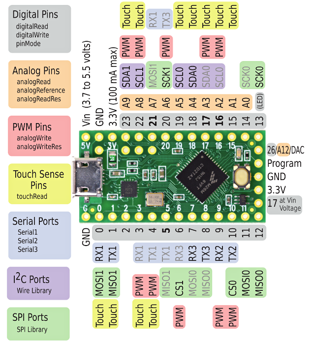
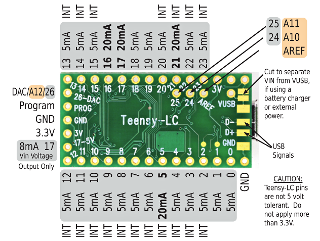
Overall, we can say that Teensy LC has much greater capabilities than we need (and it should be added that this is the most basic of the Teensy boards). It’s also not particularly expensive; in Poland, you can buy it for about 70-80 PLN, although the manufacturer priced it at less than $12. Of course, you can buy such an Arduino Nano clone from our slant-eyed friends from beyond the Great Wall for 4 times less, but as you can see, it’s worth giving a bit more for significantly greater capabilities.
GSM Module
You must remember that the project’s beginnings date back to 2017, hence some components could probably now be replaced with something newer and better. I’m not sure how it looks in 2026, but back then, the best choice for the project was the SIM800L module. It certainly still meets all requirements. The module’s capabilities, dimensions, and very (very) low price decided this - easily available on AliExpress for 12 PLN. The module is controlled via UART with AT commands, has low power consumption (up to 7 mA in IDLE, and it can even be put to sleep, then down to 2 mA). It runs GPRS with a “crazy” speed by today’s standards of up to 85.6 kbps - fortunately, for the amount of data we’ll be transmitting, this is more than sufficient 🙂. The card format is microSIM. Below is the pinout diagram.
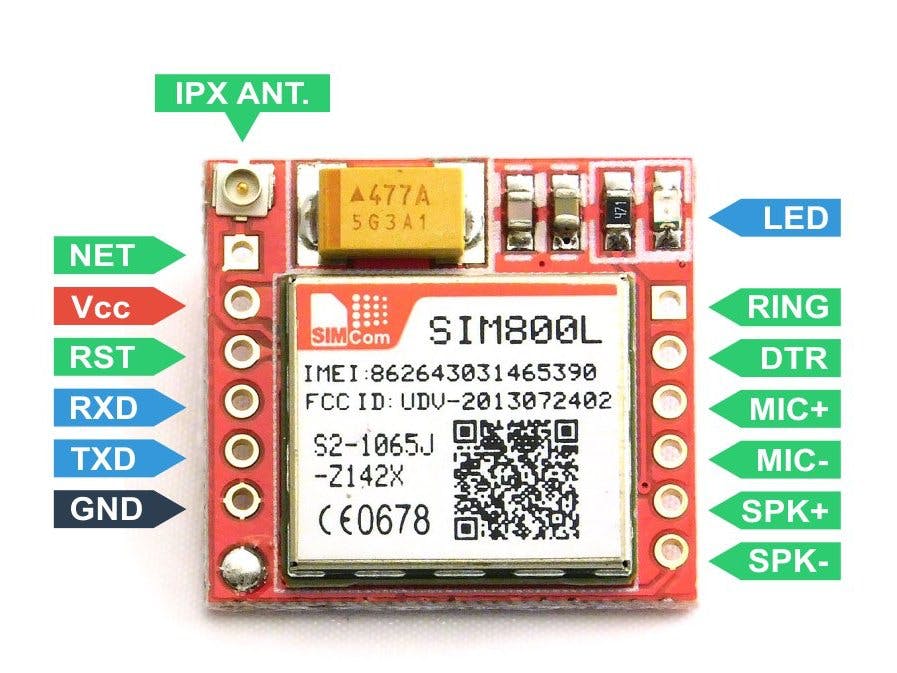
Remember not to accidentally power the module from the microcontroller. Momentary current draw during communication can theoretically reach up to 2A, which at best will cause the module to malfunction, and at worst will damage our microcontroller. Although I connected it that way and nothing exploded, I don’t recommend it 😉.
GPS Module
Regarding the satellite positioning module (as it should be properly called), I had similar assumptions as with other elements: quality, price, dimensions. The best choice turned out to be the NEO-7M module. We also have twin modules 6M and 8M to choose from - both will work well, but the former has slightly higher power consumption and only supports GPS, while 8M is a bit more expensive (though it has greater functionality). Below is a photo of the module.
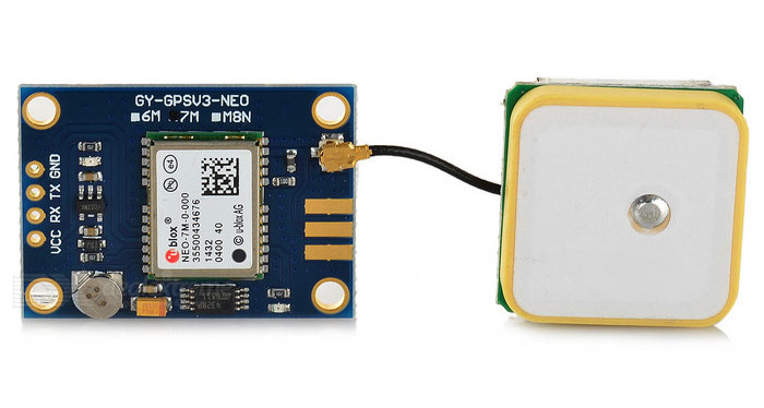
Similar to the GSM module, I suggest not overpaying and buying the module on Aliexpress. It’s almost twice as cheap (the module costs about 30 PLN).
Power Supply
The unit will be powered from the vehicle’s battery. To power the unit from the car voltage, which is about 12-14V, I used an LM2596 buck converter. It powers both the microcontroller and the GSM module.
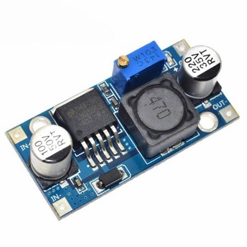
The output voltage is adjusted with the screw visible in the photo above. Models with a display are also available, but we care about maximum miniaturization.
Other Components
We’ll also need:
- PC817 optocoupler - for detecting vehicle ignition,
- BC547B transistor - for turning the GPS module on/off,
- 1N4148 rectifier diode - as protection for the optocoupler diode against reverse polarity,
- 220µF capacitor - for power supply filtering,
- 2 kΩ, 6 kΩ, and 10 kΩ resistors (best to buy yourself a set of resistors, costs pennies, and some values may need adjustment),
- connecting wires, prototyping board, 2.54mm pitch connectors, soldering iron, and all other doodads useful in electronics - pliers, wire cutters, wire stripping tool, etc.
How Should It All Work?
First, I suggest looking at the illustrative power supply diagram:
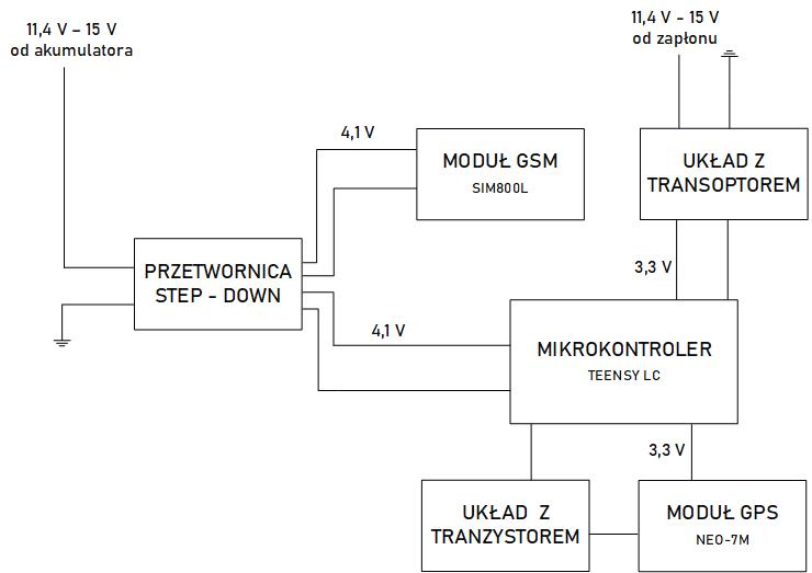
It only presents the idea of powering the unit. It gets connected to power from the vehicle’s battery, but it’s also necessary to connect it to the “ignition” signal so that we can control the interrupt in the microcontroller program, which will change the unit’s operating mode. Every car has ignition in many places; it may be easiest to pull it from the radio block. For testing purposes, we can also check with a meter in the fuse box where current appears after turning the key, where there’s constant 12V, and connect there. The supply voltage is fed to the step-down converter, which lowers the voltage to around 4.1V. Such voltage is within acceptable limits for both the microcontroller and the GSM module. An additional 200 µF capacitor was connected in series before the GSM module, whose task is to filter the power supply.
As for the ignition voltage, it’s a control signal for the microcontroller program that changes the device’s operating mode. To use this voltage as an input signal, it was connected to a circuit with an optocoupler, which allows current flow and a high signal on the microcontroller if we turn on the “ignition” in the car. This circuit consists of a PC817 optocoupler, with which on the photoemitter side a 2.2 kΩ resistor and a 1N4148 rectifier diode are connected in series, which serves as protection against burning out the optocoupler diode in case of reverse polarity. The phototransistor’s collector is connected to the 3.3V pin from Teensy, and the emitter to digital pin #15 and through a 10 kΩ resistor to the microcontroller’s ground. A circuit built this way will give us a high state on pin 15 after turning the key, which handles the interrupt changing the device’s operating mode. It sounds a bit complicated, but after reading the entire post, it should fall into place :).
The GPS module is powered from the microcontroller’s 3.3V pin via a transistor circuit. The transistor’s task is to start or stop the module depending on the state of digital pin #16, which is connected to the transistor’s base through a 6.3 kΩ resistor. The collector is connected to the GPS module’s ground, and the emitter to the microcontroller’s ground. This enables control of the module’s power supply from the program level - a high state on pin 16 causes current flow in the circuit, thereby powering the GPS module.
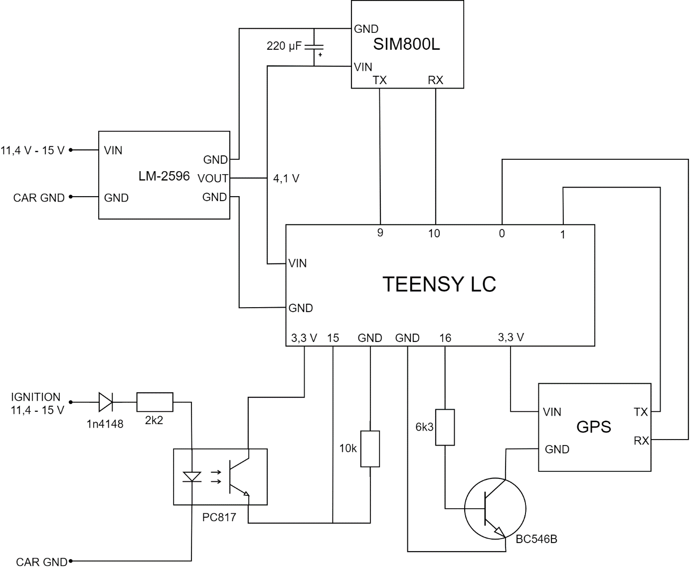
Communication between the GSM and positioning modules and the microcontroller occurs via serial interface, i.e., TX pins for sending data and RX for receiving data. The Teensy LC microcontroller has 3 independent serial ports, and each has specific pin numbers assigned on the board. The GPS module is connected to Serial 1 port, i.e., pins numbered 0 and 1, while the GSM module to Serial 2 port, i.e., pins 9 and 10.
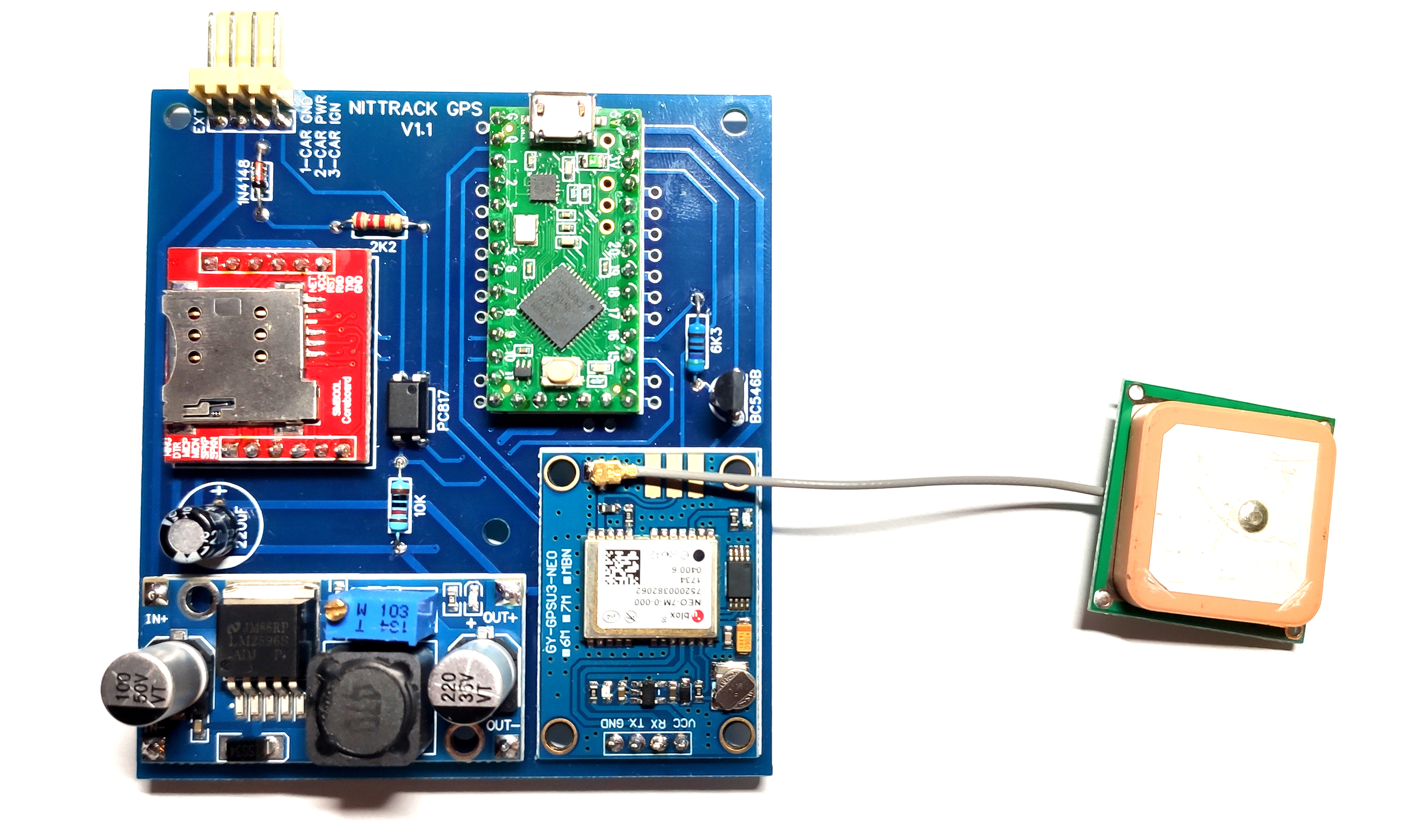
To put it all together, I soldered traces and electronic components on a universal board, to which the converter, GPS module, and microcontroller were then attached.
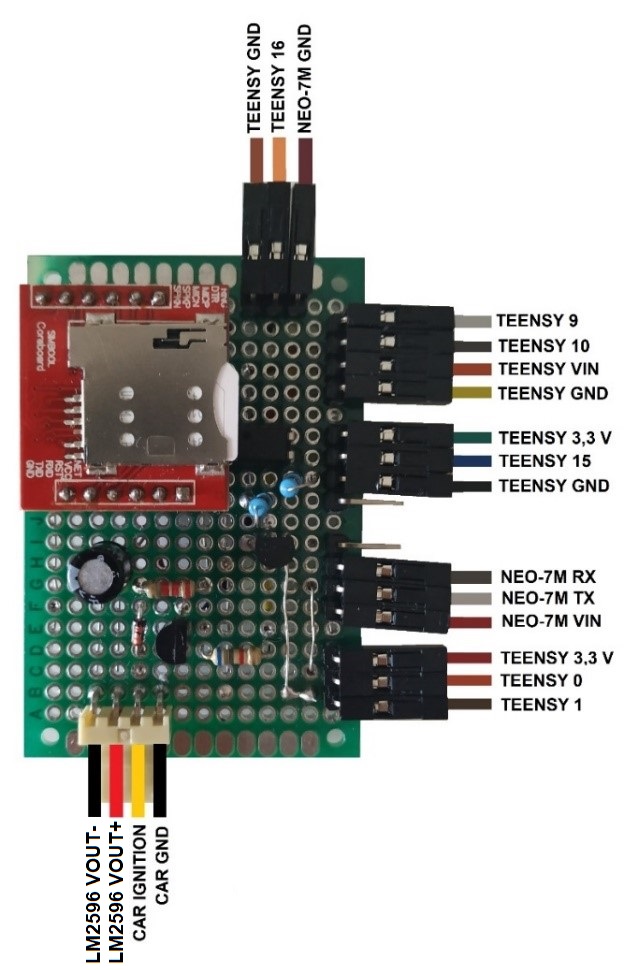
After assembling it all, it looked like this:
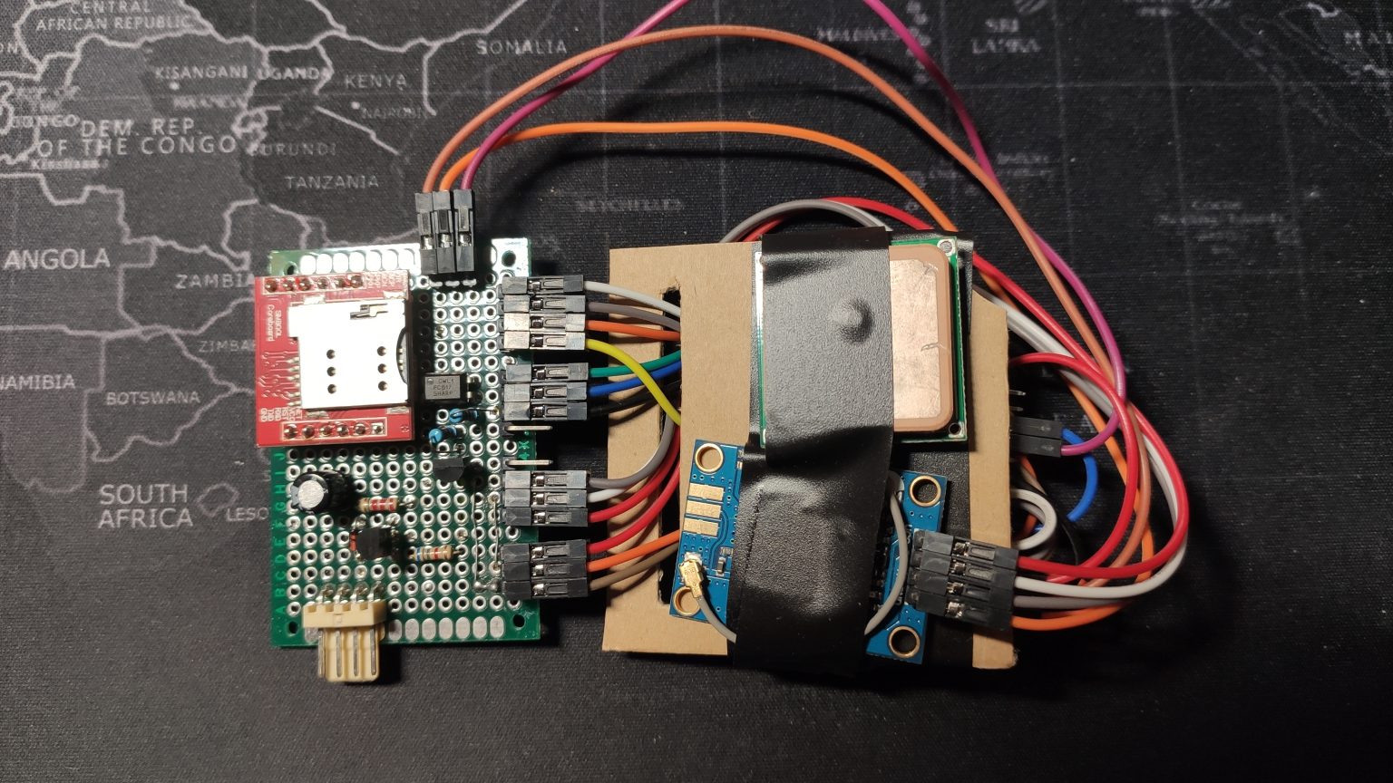
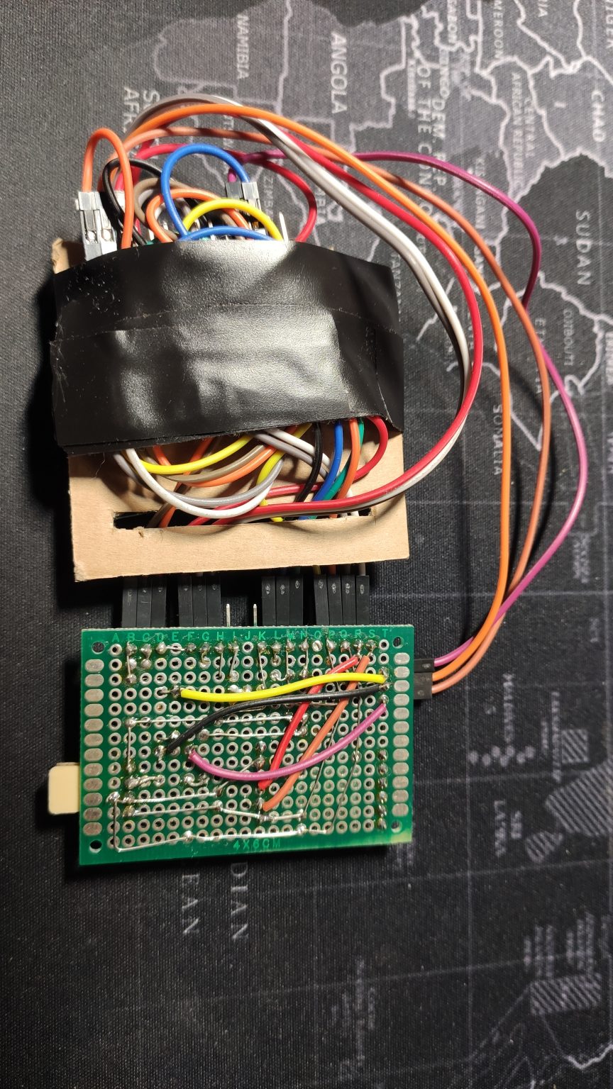
It may not be the height of elegance, but after all, it’s just a prototype. Once I knew everything was working well, I made it on a specially designed board, which I’ll discuss later.
Microcontroller Program
As is known, in Arduino we have two main functions: setup and loop. The first one is responsible for device configuration right after startup, and the instructions contained in it are executed once. Serial interfaces are initialized in it, and pin functions and interrupts are defined. The loop function contains instructions that are executed in a loop after executing instructions in the setup function. Before both loops, variables used later in the program and their default values are still defined.
At the beginning of the setup function, transmission on serial ports is initialized:
- Serial - responsible for communication between the device and the computer,
- sim800 - communication between the microcontroller and GSM module,
- gpsx - communication between the microcontroller and GPS module.
Serial.begin(9600);
sim800.begin(9600);
gpsx.begin(9600);
Next, pin A2 mode is defined as output, A1 as input and as interrupt. An interrupt is a signal from a peripheral device that causes the main program to stop and calls the interrupt handling function. In the case of the discussed program, it’s a signal change on pin A1, which is caused by turning the ignition on or off. The interrupt reacts to change, i.e., to the rising or falling edge of the control signal.
pinMode(A1, INPUT); //setting pin A1 mode as input
pinMode(A2, OUTPUT); //setting pin A2 mode as output
attachInterrupt(A1, switchMode, CHANGE); //interrupt initialization
digitalWrite(A2, HIGH); //setting default high state on pin A2
It calls the switchMode function, whose task is to set the dev_mode variable to HIGH when ignition is on and to LOW when there’s no signal from ignition. It also changes the state of pin A2, thereby starting or stopping the GPS module.
void switchMode()
{
  if (digitalRead(A1) == LOW)
  {
    dev_mode = LOW;
    digitalWrite(A2, LOW);
  }
  else
  {
    dev_mode = HIGH;
    digitalWrite(A2, HIGH);
  }
  mode0 = 0;

}
Depending on the dev_mode variable value, the main program executes different instructions, i.e., switches to position sending mode or sleep mode. In sleep mode, the mode0 variable value is first checked, whose default value is 0 and is set during each interrupt. It’s used to check if the program is entering the sleep mode loop for the first time since the interrupt. If so, the SIM800L module is set to SMS receiving mode, and then the mode0 variable is assigned the value 1. Thanks to this, when the program executes the loop again, the GSM module settings for receiving SMS won’t be duplicated.
if (mode0 == 0)
  {
    Serial.println("configuring sms reception");
    delay(500);
    sim800.println("at+cmgf=1\r\n"); //text mode for sms
    runsl();
    delay(500);
    sim800.println("at+cnmi=1,2,0,0,0\r\n"); //sms reception mode
    runsl();
    delay(500);
    mode0 = 1;
    Serial.println("Successfully configured reception");
    delay(500);
    gps_done = 0;

  }
SMS receiving mode means that upon arrival of a message, it will be immediately displayed on the serial port. The IF conditional statement checks if data is available on the port, and if so, saves it to the text_msg variable. Subsequent conditional statements use the indexOf function to catch whether the message contains the words “ON” or “PULL”. Additionally, the toUpperCase function was applied, whose task is to convert any lowercase letters to uppercase. Thanks to this, the user sending the message doesn’t have to write it in capital letters. If the message says “ON”, the dev_mode variable takes the value 1 and a high state appears on pin A2, which consequently causes the GPS module to wake up and switch to location data sending mode. A message with the content “PULL” causes the GPS module to start, and then the gps_read function is executed until the gps_done variable is not different from zero. The gps_done variable takes the value 1 only after successfully sending the location. This means that the program will always “wait” to obtain the correct location, and only then will the GPS module be turned off.
else
  {
    if(sim800.available()>0)
    {
      text_msg = sim800.readString();
      Serial.println(text_msg);
      delay(10);
    }

    if(text_msg.toUpperCase().indexOf("ON")>=0)
    {
      digitalWrite(A2, HIGH);
      dev_mode = 1;
      text_msg = "";
    }

    if(text_msg.toUpperCase().indexOf("PULL")>=0)
    {
        digitalWrite(A2, HIGH);

        while (gps_done == 0)
        {
          gps_read();
        }
        digitalWrite(A2, LOW);
        gps_done = 0;
        text_msg = "";
    }
  }
The location transmission mode is active if the dev_mode variable has the value 1. The gps_read function is then called. In the WHILE loop, it’s checked whether data from the positioning module’s serial port is available. If not, a message is displayed about checking the correctness of the GPS module connection. If data is available, the displayInfo function is called. At its beginning, it’s checked whether the available data is correct, i.e., whether the GPS module has already established contact with satellites and is able to provide the correct position. If so, using a series of AT commands sent via the serial port to the GSM module, a connection with the server is established and a POST frame is created, which contains the following information:
- latitude and longitude,
- speed in km/h,
- position acquisition time,
- number of satellites,
- direction of movement,
- device status,
- device token.
sim800.println("at+httppara=\"URL\",\"http://SERVER_IP/nittrack/dodaj.php\"\r\n"); //write your server IP
    runsl();
    delay(1000);
    sim800.println("at+httppara=\"CONTENT\",\"application/x-www-form-urlencoded\"\r\n");
    runsl();
    delay(500);

      String urlData = "lng=";
      urlData += String(gps.location.lng(), 6);
      urlData += "&lat=";
      urlData += String(gps.location.lat(), 6);
      urlData += "&speed=";
      urlData += String(gps.speed.kmph());
      urlData += "&gps_time=";
      urlData += String(gps.time.value());
      urlData += "&satellites=";
      urlData += String(gps.satellites.value());
      urlData += "&course=";
      urlData += String(gps.course.deg());
      urlData += "&device_status=";
      urlData += String("drive");
      urlData += "&token=";
      urlData += String(token);
The frame is saved to the urlData variable. Then, using the length function, its length is determined - this is a necessary parameter for a POST request.
    //display data frame and calculate its length
    Serial.println(urlData);
    lengthx = String(urlData.length());

    sim800.println("at+httpdata=" + lengthx + ",10000\r\n");
    delay(300);
    sim800.println(urlData);
    delay(6700);
    sim800.println("at+httpaction=1\r\n");
    runsl();
    delay(3000);
At the end of the loop, the connection with the server is interrupted until the next location data is obtained.
It sounds a bit complicated, but it will be easier to understand the program’s operation based on the algorithm:
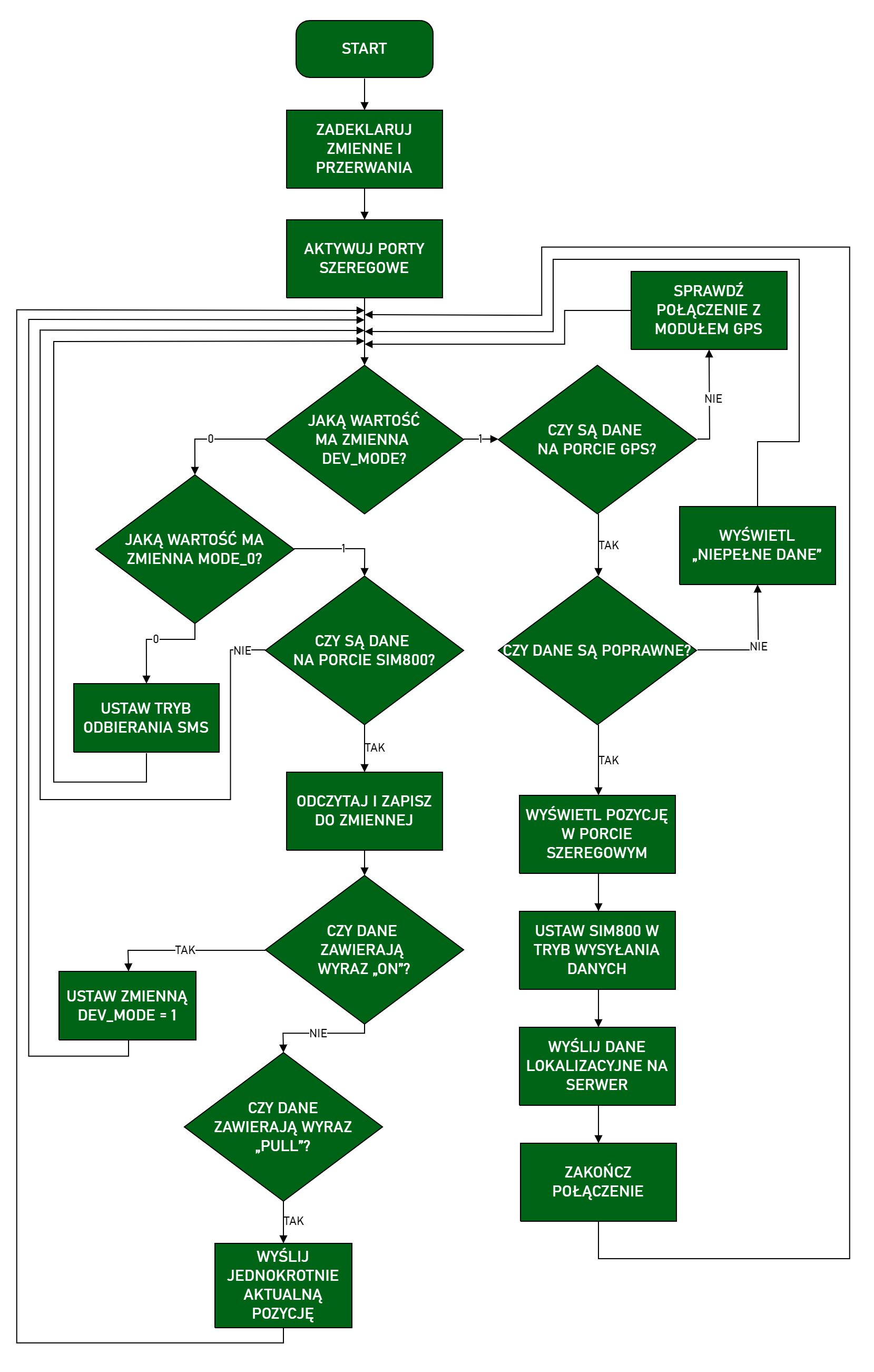
You can download the full program code from github.
Power Consumption
As I mentioned in the concept, low power consumption is quite an important issue in the case of a tracking unit. Nobody wants their car battery to die after a week of standing because we have some piece of electronics inside. So I conducted power consumption tests covering all device operating cycles, i.e.:
- unit startup,
- satellite search,
- sending location data to the server,
- transition from working mode to sleep and vice versa,
- performing the “PULL” action, i.e., a single location retrieval.
Measurements were made with an Owon B35T+ multimeter with the ability to transmit data via Bluetooth interface. The measurement frequency was 2 Hz. Data was transmitted to a smartphone with a dedicated application enabling saving readings to a CSV file.
The chart below shows the relationship between current intensity and time starting from unit startup, through network login and sending location data to the server. The supply voltage was approximately 14.4 V.
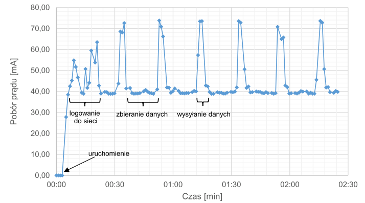
After starting the device, it logs into the GSM network and basic device configuration enabling GPRS connection occurs. This process takes about 20 seconds. During this time, there are clear fluctuations in current intensity, whose value ranges from about 40 mA to 65 mA. Then the device waits for correct location data from the GPS module, drawing about 39-41 mA. After receiving correct data from satellites, the unit sends them to the server. At this stage, a significant jump in current intensity is visible, which can reach 80 mA, but this state lasts a maximum of 3 seconds because after this time the program ends the connection with the server.
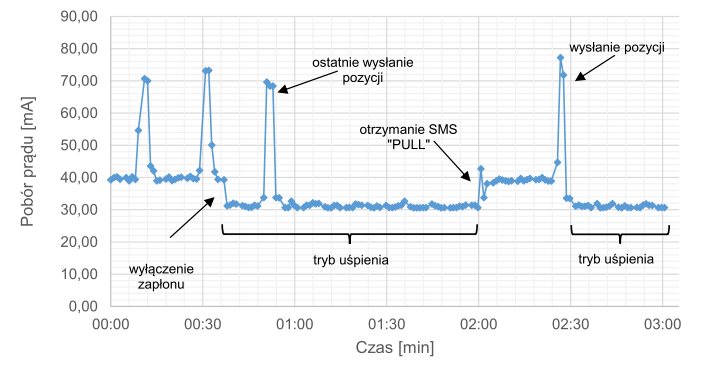
In the next chart, initially the unit works in position sending mode, after which the ignition is turned off and the device goes into sleep mode. A single position transmission is visible after transitioning to sleep state. This happens because if ignition is turned off during the execution of the sending loop, the program structure allows this process to be completed and only then is the GSM module set to SMS waiting mode. Transitioning to sleep mode causes power consumption to decrease to the range of 30-32 mA. The chart also shows polling the sleeping unit for current position, i.e., receiving an SMS with the content “PULL”. An increase in consumption of about 10 mA is noticeable, followed by a jump to nearly 80 mA, i.e., sending the position and re-entering sleep state. The supply voltage was approximately 14.4 V with ignition on and about 12.9 V with ignition off.
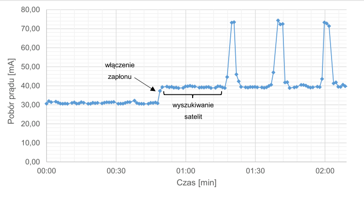
In the last chart, initially the device was in standby mode, and then the ignition was turned on. For the next 30 seconds, the GPS module tried to obtain a correct signal from satellites. You can notice that during this time power consumption didn’t change. This means that during satellite signal search, power consumption is similar to when receiving their signal.
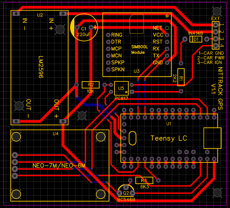
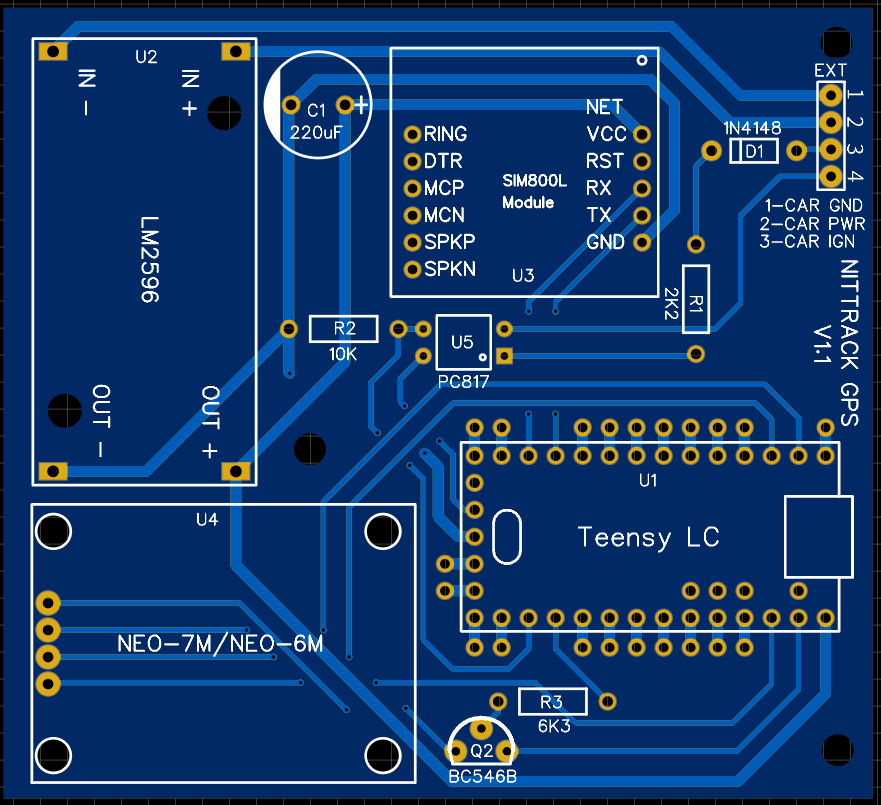
Target Board
After tests and examinations of the device assembled this way, I decided to make a dedicated PCB board that only requires soldering the component parts. I designed the board in the EasyEDA program, which I wholeheartedly recommend. It’s very intuitive, easy to use, has plenty of ready-made components, and is free. Additionally, it integrates with the JLC PCB shop, where we can directly order designed boards. This is what the finished project looked like:
The boards cost I think $8 for 10 pieces, which I consider a great price considering that nothing can be faulted with the manufacturing quality, shipping speed, and customer service. Soldered, the finished device looks pretty nice:
Interestingly, on the finished board I had to change the resistor value in the transistor circuit because it didn’t want to start. I did it experimentally because the calculations didn’t really add up here.
That’s all about the tracking unit. Remember to change the APN values in the program depending on which operator’s SIM card we have.
In the next post, the web application handling the unit will be presented. Claude
Comments